Build a system to the required length. Decide which sections carry material and which deliver it through perforations. View the complete lance and its parts list.
EXPLORE THE SYSTEM COMPONENTS
The complete JG Ø13 mm system
Read the assembly from the bottom: 1 — tip, 2 — section next to the tip, 3 — connector, 4 — extension, 5 — end fitting or further extension, 6 — packer / adapter connection. Select a number or component. Solid and perforated versions are shown side by side.
Exploded diagram, not to scale. Components shown side by side are alternative versions.
BUILD YOUR LANCE
The whole system. Section by section.
Enter the lance length and perforated zone length. Then select sections to view their specifications or change the delivery zone.
* Mining packers and couplers for the Ø21,3 mm system are available on enquiry and are not included in this configurator.
Ø13 mm: sections of 500 or 1000 mm. With 500 mm sections, the perforated length can be set in 0.5 m steps.
Select the tip, section, connector or connection to view its detail. On a phone, swipe the diagram sideways. Assembly length is the sum of section lengths; 500 mm sections are shown at half the length of 1000 mm sections. Accessories are not to scale.
YOUR ASSEMBLY
Parts required for assembly
Connectors are counted between sections: the number of sections minus one. The connection and tip are listed separately. The driving plug, hose and pump are worksite accessories.
How many identical lances do you need?
The diagram and component list above show one lance. Each assembly has the same configuration.
Material exits through the side holes of the lance. The JG-NOSHOOTER tip closes its end. The position of the perforated sections defines the injection zone.
Ø13 system
JG-END-PER + JG-NOSHOOTER
Ø21,3 system
JG-PER 21,3 + JG-NOSHOOTER 21,3
02 / LANCE END
Solid section + ejectable tip
The solid lance carries material to the end of the system. JG-SHOOTER is the ejectable tip intended for this configuration.
Ø13 system
JG-CONNECT + JG-SHOOTER
Ø21,3 system
JG-CONNECT 21,3 + JG-SHOOTER 21,3
03 / PERFORATION + SHOOTER
Perforation + ejectable tip
Perforated sections with an ejectable tip: side outlets and an opening at the system end.
Ø13 system
JG-CONNECT-PER + JG-SHOOTER
Ø21,3 system
JG-PER 21,3 + JG-SHOOTER 21,3
A DETAIL THAT MAKES ASSEMBLY EASIER
Flat surfaces. A secure wrench grip.
Wrench flats let you hold the component while tightening the connection. Place the wrench jaws on the prepared flat surfaces.
In the Ø21,3 system, the 3/8″–1/4″ adapter also has wrench flats. JG-CONNECTOR 21,3 has a different geometry and is shown separately in the diagram.
SYSTEM COMPARISON
Different diameters and connections.
Feature
JG Ø13 mm
JG Ø21,3 mm
Internal channel
Ø9 mm
Ø14,3 mm
Section length
500 / 1000 mm
1000 mm
Perforation
Ø3,8 mm · 16 holes/m
Ø5,5 mm · 16 holes/m
Joining sections
JG-CONNECTOR 14 coupling, 1/4″ female thread
JG-CONNECTOR 21,3, 3/8″ male threads
Starting section
JG-END-PER for the fixed tip; JG-CONNECT / JG-CONNECT-PER for the ejectable tip
JG-PER / JG-CONNECT with a male thread for mounting the tip
Extension
JG-CONNECT / JG-CONNECT-PER
JG-CONNECT-S / JG-PER-S, female threads at both ends
LANCE ASSEMBLY AND DRIVING
Tighten first. Then drive.
Drive the lance in sections. The JG-HAMMPLUG driving plug protects the threaded connection and transfers impacts to the lance. For use with a hammer drill, it connects to a JG-HAMMPOD adapter matched to the tool holder: SDS+ or SDS-MAX.
Protect threads from impact.
Before driving, tighten the components correctly and fit the driving plug. Do not strike an exposed thread or drive a loosely assembled system: this can damage the threads. Use the wrench flats for tightening.
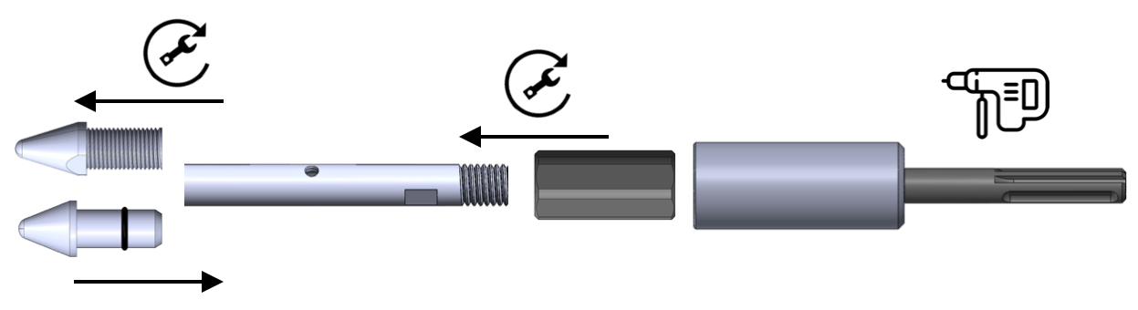
1. Fit the tip and driving plug
Fit the push-in tip JG-SHOOTER or screw the fixed tip JG-NOSHOOTER into the appropriate starting section.
At the opposite end, fit JG-HAMMPLUG.
Attach JG-HAMMPOD and drive the section using a hammer drill.
From left: tip → lance section → JG-HAMMPLUG → JG-HAMMPOD.
2. Add the next section
Remove the adapter and unscrew JG-HAMMPLUG.
Screw on JG-CONNECTOR 14, then connect the next lance section to it.
Refit the driving plug at the free end. Repeat driving and extending until the design depth is reached.
Starting section → connector → extension section.
Fit the material delivery connection after driving is complete.
Tighten first. Then drive.
Drive the lance in sections. The JG-HAMMPLUG 21,3 driving plug protects the threaded connection and transfers impacts to the lance. For use with a hammer drill, it connects to a JG-HAMMPOD adapter matched to the tool holder: SDS+ or SDS-MAX.
Protect threads from impact.
Before driving, tighten the components correctly and fit the driving plug. Do not strike an exposed thread or drive a loosely assembled system: this can damage the threads. Use the wrench flats for tightening.
1. Fit the tip and driving plug
Fit the end with tip JG-SHOOTER 21,3 or screw on the fixed tip JG-NOSHOOTER 21,3 into the appropriate starting section.
Screw into the free end of the lance JG-HAMMPLUG 21,3.
Attach JG-HAMMPOD and drive the section using a hammer drill.
From left: tip → lance section → JG-HAMMPLUG 21,3 → JG-HAMMPOD.
2. Add the next section
Remove the adapter and unscrew JG-HAMMPLUG 21,3.
Screw on JG-CONNECTOR 21,3, then connect the next lance section to it.
Refit the driving plug at the free end. Repeat driving and extending until the design depth is reached.
Further sections and connection adapter. Below: cross-section of the assembled lance.
Fit the material delivery connection after driving is complete.