
DESIGN · DELIVERY · CONTROL
Injection pumps.
Choose how you work.
Compare drive types, delivery paths and operation. Pump pressure is one system parameter: selection must also account for the required flow and permitted material.
EXPLORE THE MACHINE COMPONENTS
Choose a design. Select a detail.
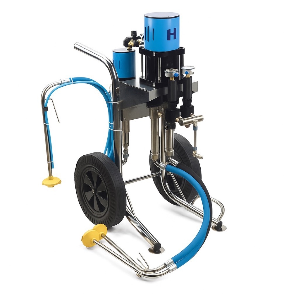
PI-PUMP 3K — machine design.
Pneumatic piston pump · separate material paths
PI-PUMP 3K
The pneumatic drive moves the pistons, while separate paths carry components to the injection head. We match the third channel's function and metering ratio to the material and system configuration.
- Recommended operating range
- 0–220 bar
- Maximum outlet pressure
- 240 bar
- Free discharge
- up to 9 l/min
- Weight
- 45 kg
Free discharge: up to 9 l/min; under load, output depends on pressure and material. Maximum inlet air pressure: 8 bar.
Pneumatic drive
Compressed air drives the pistons. Select another point on the illustration to explore that component's function.
WHAT THE DESIGN CHANGES
Three ways to deliver material
| Selection | Diaphragm · 4000 | Pneumatic piston · 3K | Manual piston · type |
|---|---|---|---|
| What drives delivery | Electric motor and diaphragm mechanism; valves direct the flow. | Compressed air moves the pistons; separate paths carry components to the head. | Lever strokes made by the operator. |
| Worksite setup | Electrical supply, a suitable tank and delivery control at the outlet. | Compressor with adequate output, air preparation and channel configuration. | No external drive; requires access to the lever and a stable connection. |
| Monitoring operation | Quiet operation requires careful monitoring of pressure and actual delivery. | Observe the piston stroke pattern together with the pressure gauge and delivery rate. | The operator feels changes in resistance and controls each dose through lever strokes. |
| Selection limitation | Flow depends on the operating point. Prolonged use can heat the system and affect the material being delivered. | Mobility is limited by the air supply. The ratio and function of each channel must be agreed. | Operator effort and time; seal wear depends on the material and handling. |
| What determines the choice | Material, work rate, tank and control ergonomics. | Need for separate flow paths, a compatible head and actual air demand. | Small volume, access to the injection point and compatibility of the specific model with the material. |
Choose a drive suited to the task size and worksite conditions.
1K, 2K and 3K — material paths
One delivery path
A single path can also carry a prepared mix if the pump is suitable. Plan delivery and cleaning within the material's working time.
Separate components
Components can reach the head separately and combine close to the injection point. The system must provide the required metering ratio and adequate mixing.
An additional path
The third channel can be used for flushing or an additional component, depending on configuration. The 3K designation alone does not specify the channel's function or mixing ratio.
A lower setting helps you monitor operation
With a diaphragm pump, assess delivery using material consumption and the pressure gauge. Drive noise alone says little about flow.
What do you observe while delivery is open?
The regulator lets you match pressure to the injection task. Watch the gauge and delivery rate together to respond to changing resistance.
If pressure falls, check material intake, valve position and connection tightness. Compare the reading with the delivery rate.
Monitor more than one variable
Check whether material is drawn from the tank, whether connections are tight and where injected material appears.
The safety valve is not a substitute for the working pressure regulator. Before disconnecting or checking for blockages, depressurise the system according to the equipment instructions.
Manual pump: lever and aligned connection
With a conical nipple, the coupler should stay aligned with the connection. Sideways hose movement and misalignment make proper contact harder to maintain. Plan for operating the lever and holding the coupler at the same time.
When the coupler needs manual support, plan for two people: one stabilises the connection and the other operates the lever.
A flat-head coupler holds the connection without continuous pressure from the operator. It makes longer injections easier and leaves the operator's hands free to use the pump.
ACTUAL INJECTION HEAD VERSIONS
Choose the family and number of flow paths
The number of paths, weight and servicing method affect handling. Choose the version to suit the material, required metering ratio and flushing method.
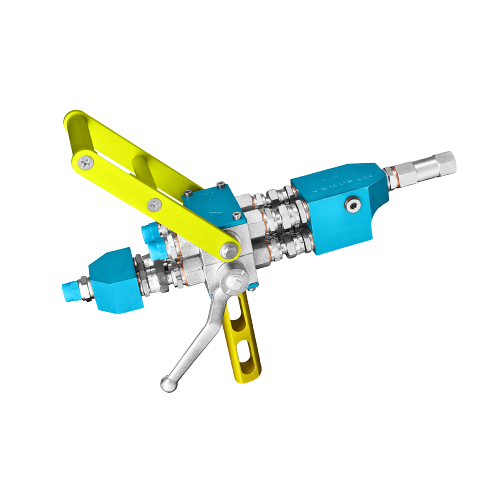
Injection Gun 3K
Three-channel version in stainless steel and anodised aluminium. This family has two independent cleaning channels.
- Weight
- 3,97 kg
- Maximum pressure
- 250 bar
- Inlet / outlet
- 1/4″ BSP / M10×1
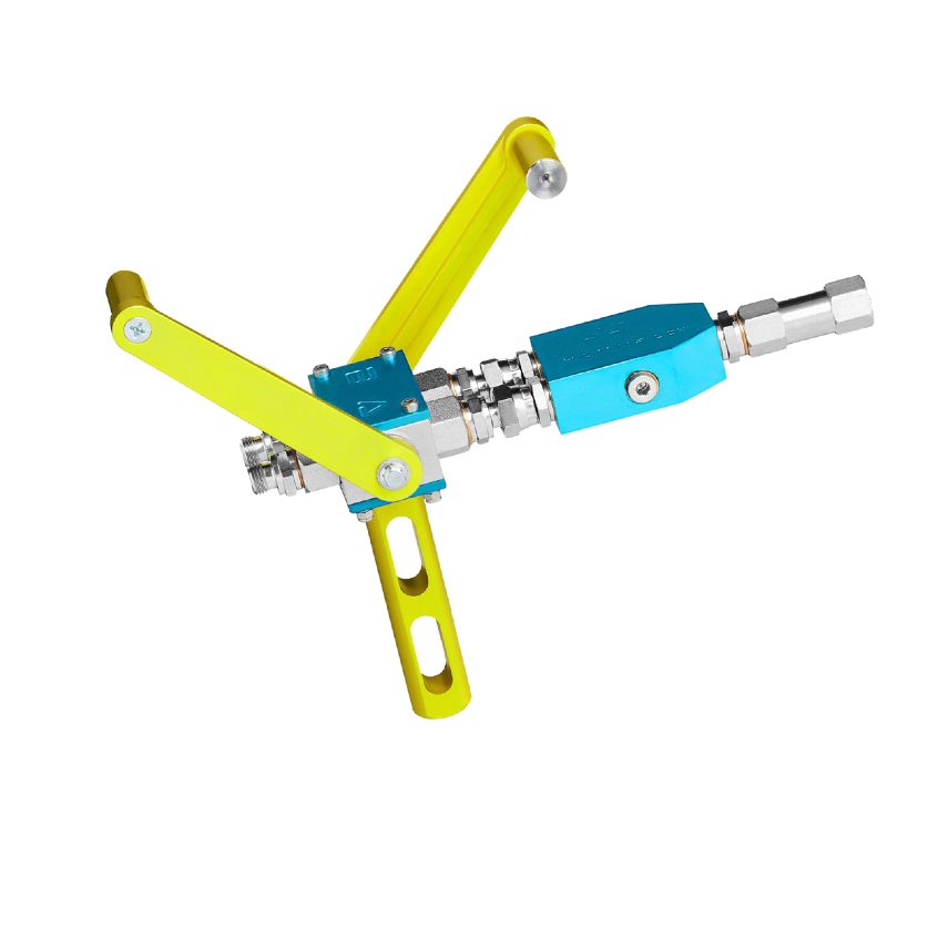
Injection Gun 2K
Two-channel version in stainless steel and anodised aluminium. Valve and flushing selection depends on the specific assembly.
- Weight
- 1,53 kg
- Maximum pressure
- 250 bar
- Inlet / outlet
- 1/4″ BSP / M10×1
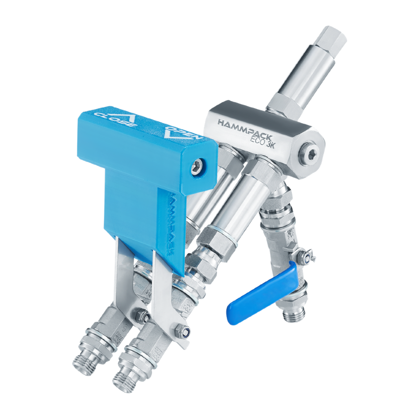
ECO 3K
The third path can be used for flushing or an additional component. Servicing uses replaceable valves.
- Weight
- 1,13 kg
- Maximum pressure
- 250 bar
- Inlet / outlet
- 1/4″ BSP / M10×1
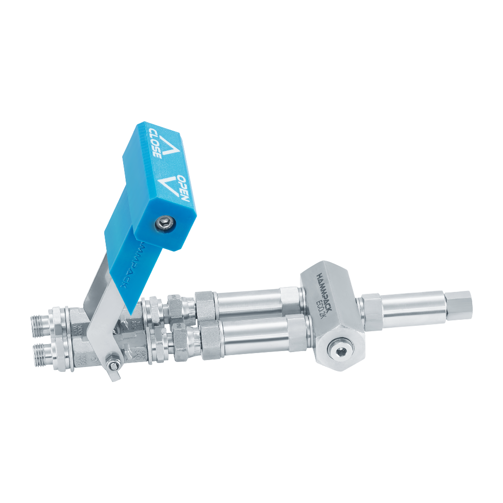
ECO 2K
Two-channel version. Compact design with replaceable valves.
- Weight
- 0,94 kg
- Maximum pressure
- 250 bar
- Inlet / outlet
- 1/4″ BSP / M10×1
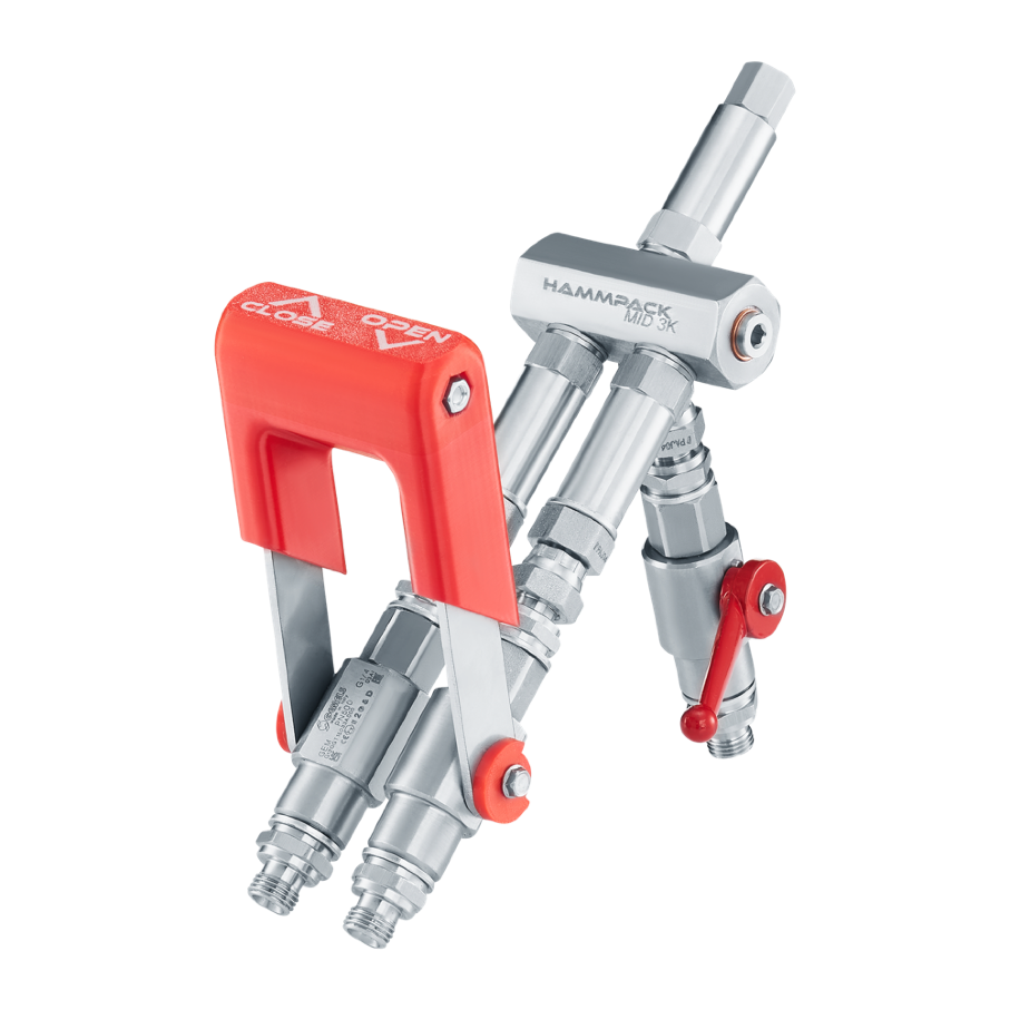
MID 3K
A third path and sliding Open/Close control. Designed for valve cleaning and refurbishment.
- Weight
- 1,58 kg
- Maximum pressure
- 250 bar
- Inlet / outlet
- 1/4″ BSP / M10×1
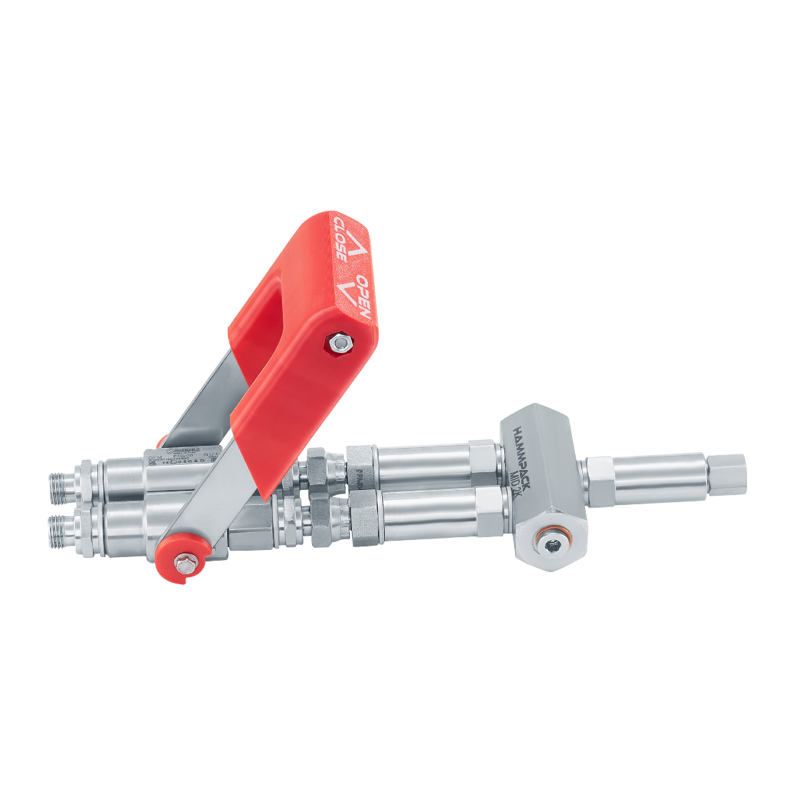
MID 2K
Two-channel version with sliding Open/Close control and serviceable valves.
- Weight
- 1,26 kg
- Maximum pressure
- 250 bar
- Inlet / outlet
- 1/4″ BSP / M10×1
Explore the 3K head and BIGONE mixer
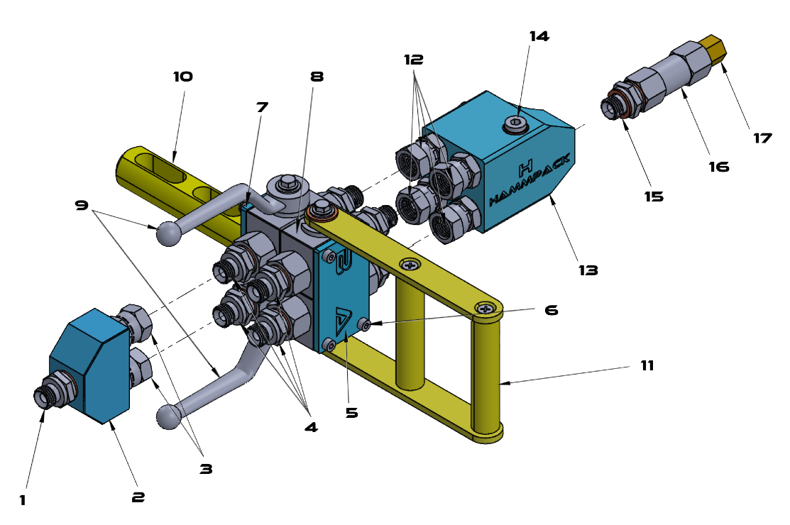
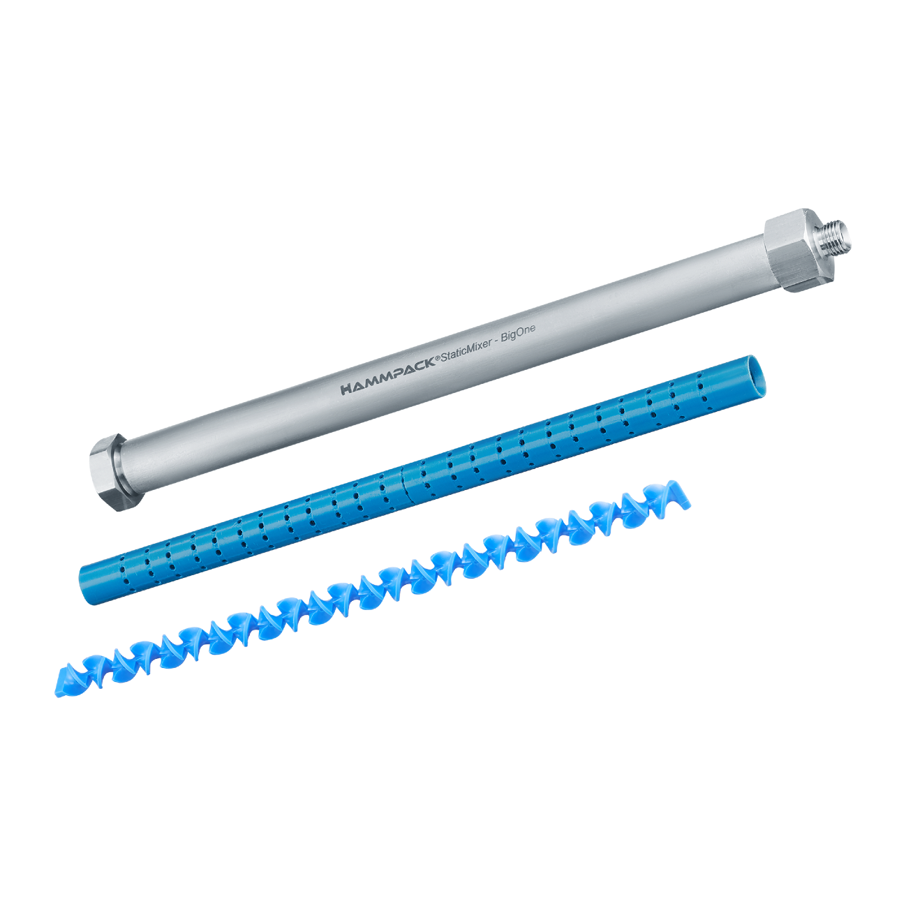
BIGONE static mixer
1/4″ male thread, M10×1 outlet, 300 mm length, 0,51 kg weight. The mixer tube and insert form part of the flow path after the head. Their selection affects mixing length and delivery resistance.
The injection head completes the system
Choose the number of channels, connections and handling method. Injection Gun, ECO and MID families differ in weight, valve design and servicing. Similar appearance does not make 2K and 3K versions interchangeable.
| Family | 2K / 3K weight | Practical difference |
|---|---|---|
| Injection Gun | 1,53 / 3,97 kg | Stainless steel and anodised aluminium; separate cleaning paths depending on version. |
| ECO | 0,94 / 1,13 kg | Replaceable valves; an additional path in the 3K version. |
| MID | 1,26 / 1,58 kg | Designed for valve cleaning and refurbishment; an additional path in 3K. |
Head specifications: maximum 250 bar, 1/4″ BSP inlet, M10×1 outlet. Match working pressure to the hose, coupler and packer as well.
Prepare equipment for the next job
- Remove material before it cures inside the pump, valves and head. Choose the cleaning method according to the equipment and material instructions.
- Before disconnecting, follow the depressurisation procedure for the specific equipment.
- Check filters, valves, seals and coupler. Replace worn components with compatible parts.
- On PI-PUMP 3K, check the fluid in the piston-rod lubrication chamber according to the equipment data sheet. Use the recommended preservation procedure during downtime.
Define the operating point before choosing a model
Match the pump to the material, required delivery rate and working pressure. Output may fall as resistance increases; free-discharge output compares equipment without load.
PI-PUMP 3K requires a compressor and a head suited to the components. For PI-PUMP 4000, select the tank capacity and delivery control. With a manual pump, allow room for lever movement and convenient access to the packer.
Changes in delivery rate need observation
If delivery decreases, check the flow path and material condition before increasing pressure. Compare the gauge reading with the quantity of material delivered.