
CONSTRUCTION JOINT INJECTION SYSTEM
Injection hoses.
Explore the complete system.
The injection hose stays inside the structure. Accessible ends let you inject material into the prepared section later. Plan the layout, connections and access before constructing the element.
INJECTION HOSE SYSTEM
Choose a number. Explore the component.
On the left, the hose layout. Beside it, a photograph and the selected component's function.
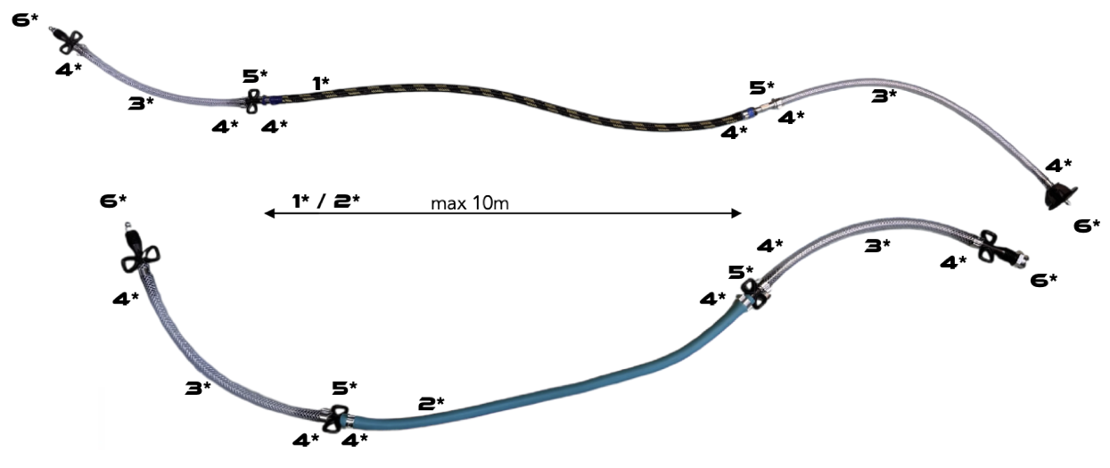
Divide the 100 m roll into working sections up to 10 m long. Terminate each section with accessible injection points.
ORDER PARTS LIST
How much hose and how many accessories do you need?
Enter the joint length to be sealed. The calculator adds overlaps and divides the hose into sections with two accessible ends.
HOSE IN THE STRUCTURE / OPERATING PRINCIPLE
Plan access. Seal the construction joint.
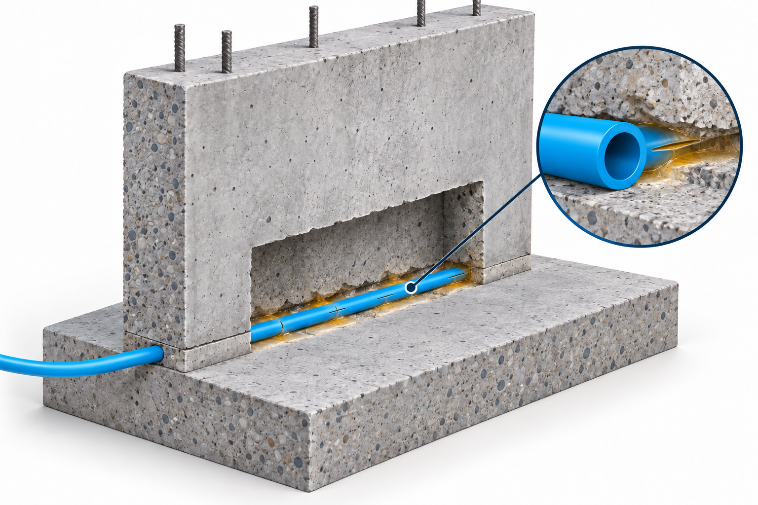
The hose is laid before the next concrete pour. It remains in the construction joint, while the accessible ends let you inject material into this zone later.
Delivery along the joint
Slits in the injection section open during resin delivery, allowing material to spread along the construction joint.
Access after concreting
Feed ends remain accessible. Labelling both ends identifies each individual section.
A layout matched to the structure
The hose can follow the slab-to-wall joint or the boundaries between successive concrete pours.
The hose alone does not seal the joint: it provides a path for a suitable injection material. Re-injection depends on the system and material used.
BEFORE CONCRETING
Injection hose, fixings and accessible ends
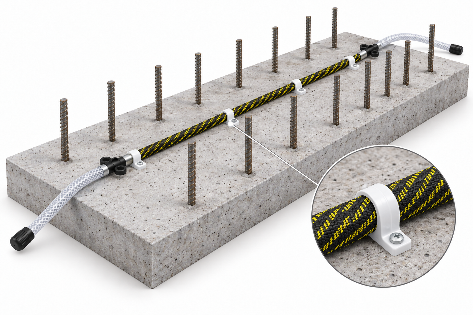
The braided section remains fixed to the substrate. Transparent reinforced feed hoses connect it to accessible injection points.
Prepare the substrate
Remove loose fragments and contamination. The hose should lie against the prepared concrete.
Lay and secure
Route the hose in gentle curves, without kinks or crushing. Fixings must hold its position during concreting too.
Connect and label
Match connectors to hose diameters, secure the connections and label both ends of each section.
Check before covering
Check fixings, routing and access to the ends. Record section positions in the as-built documentation.
LAYOUT DIMENSIONS
Spacing, section length and overlap
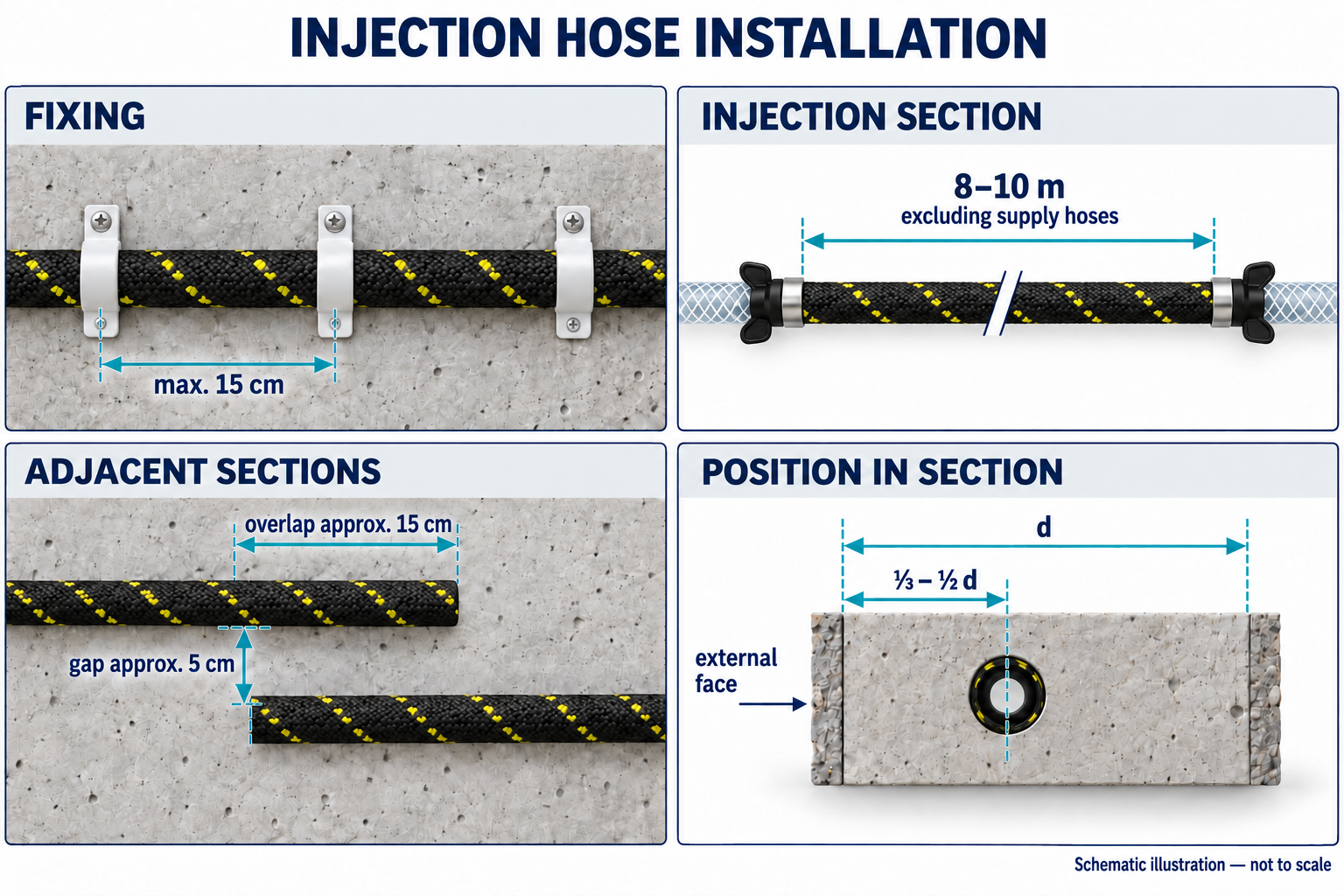
Distinguish working hose length from feed hose length. Run adjacent sections parallel through the overlap zone, maintaining the gap.
- Fixings
- max. 15 cm
- Working section
- 8–10 m
- Section overlap
- approx. 15 / 5 cm
- Position
- ⅓–½ d
Spacing between successive clips; use closer spacing where geometry requires it.
Section length excluding feed hoses. A 100 m roll supplies multiple sections.
Longitudinal overlap approximately 15 cm, with approximately 5 cm between parallel hoses.
Measured from the outside face of the element; establish the final route in the sealing design.
THREE INJECTION HOSES
Choose the hose diameter and construction
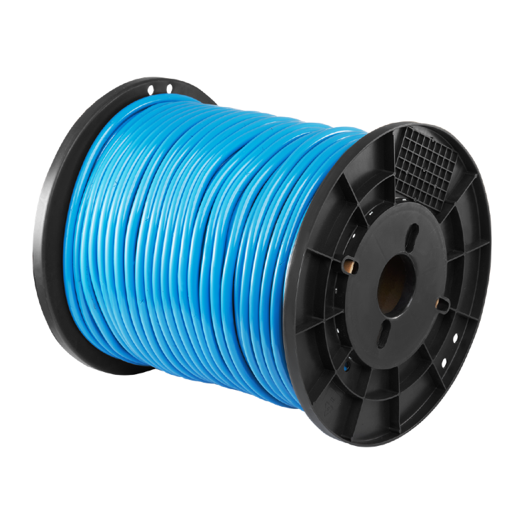
HO-HOSE 5
Unbraided injection hose for construction joints. Plan the sections and accessible ends before concreting.
- Internal / external diameter
- 5 / 11 mm
- Outlet openings
- 2 mm
- Supply format
- 100 m roll
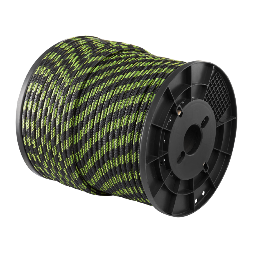
HO-HOSE/B 5
Perforated hose with textile braiding for construction-joint injection. Installed before concreting, it delivers material along the joint to be sealed.
- Internal / external diameter
- 5 / 11 mm
- Outlet openings
- 2 mm
- Supply format
- 100 m roll
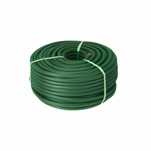
HO-HOSE 18 mm
SMARTHOSE system hose for embedding in construction joints. Secure it to a smooth, clean surface using HO-KEEPER clips and protect the braiding during installation.
- Internal / external diameter
- 8 / 18 mm
- Outlet openings
- 3 mm
- Supply length
- 100 m roll
Choose the hose version and supply length on the B2B platform.
SEPARATE CONNECTION COMPONENTS
Injection point and connector
The steel HO-END 8 end fitting, plastic HO-INJECT packer and HO-CONNECT 6 connector have different roles. Match them by diameter and the geometry of the specific system.
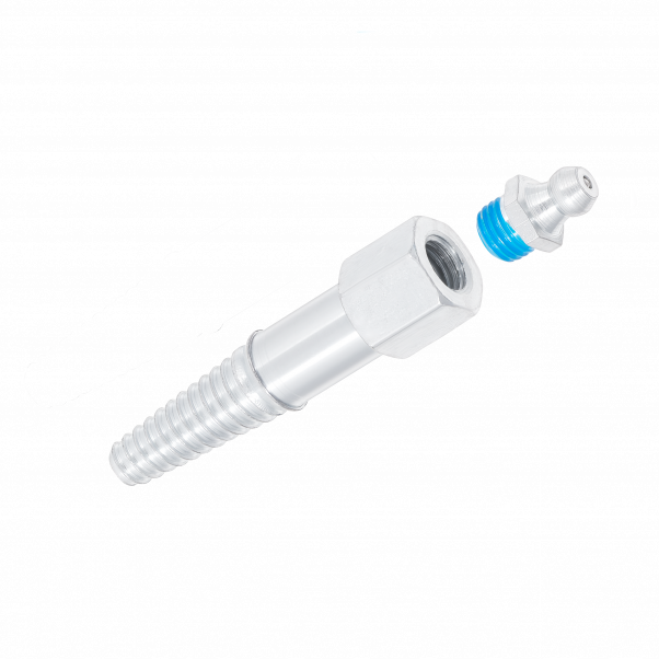
HO-END 8
Steel injection point for hoses. Choose the nipple together with a compatible coupler, hose diameter and connection securing method.
- Material / length
- steel / 55 mm
- Passage
- 3 mm
- Hose — internal diameter
- 4–8 mm
- Nipple thread
- M6×1
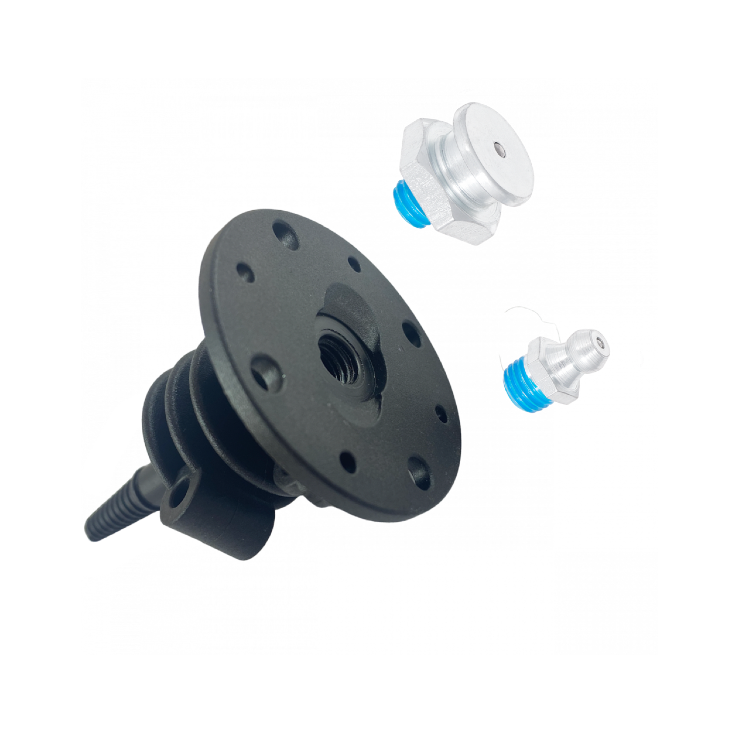
HO-INJECT
Formwork packer for an injection hose. It provides a system connection point; choose a nipple to match your coupler and ensure access after construction.
- Material / length
- plastic / 73 mm
- Passage
- 2,5 mm
- Hose — internal diameter
- 5–7 mm
- Nipple
- conical or flat-head · M8×1,25
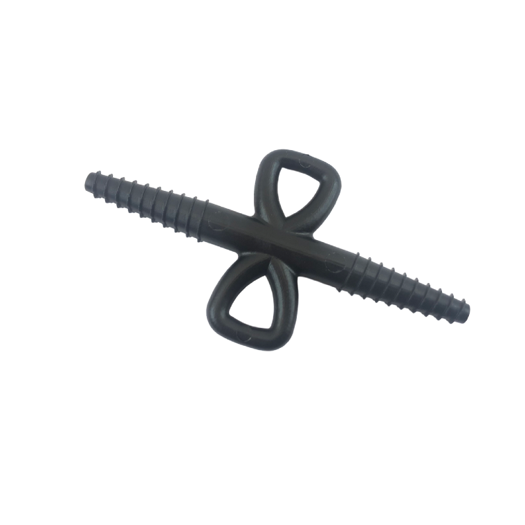
HO-CONNECT 6
Plastic connector joining the injection hose to the feed hose. Select clamps and check that both sides of the connection are secure.
- Material / length
- plastic / 79 mm
- Passage
- 2,5 mm
- Hose — internal diameter
- 5–7 mm
- Version
- anti-twist thread
For HO-HOSE 18 mm, select SMARTHOSE fittings matched to the 8 mm channel and 18 mm external diameter.
Plan connections together with the layout
Working section
Determine the hose route in the construction joint and divide it into sections. Position fixings and accessible ends before concreting.
Secured connections
Check hose diameters, the correct connector and clamps. The diagram distinguishes the injection hose from the feed section.
Access after construction
Route and label the ends according to the system design. Before later injection, identify the correct section and match the coupler to the packers.
Select a complete system
Provide the joint length, number of sections and feed-end arrangement. We will select the hose, feed lines, connectors and fixings. If you plan re-injection, we will account for a system and material intended for that use.